-40%
150W 10A Constant Current Electronic Load Tester Battery Discharge Capacity Test
$ 6.36
- Description
- Size Guide
Description
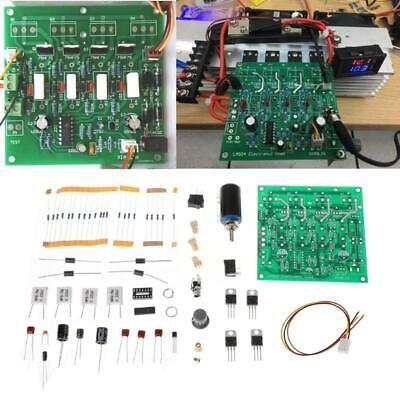
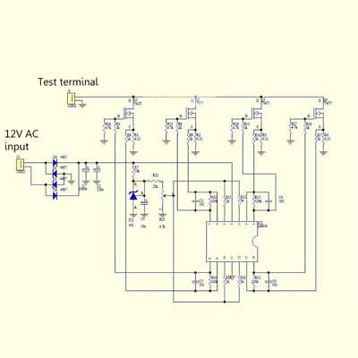
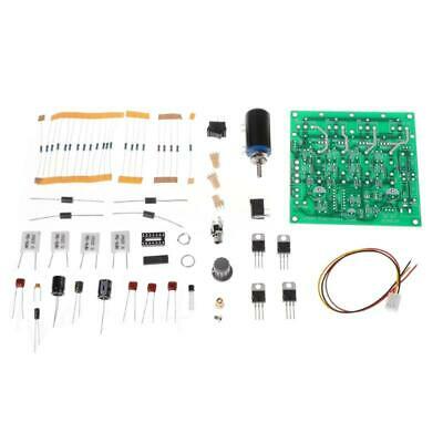
Features:-The basic circuit form is TL431 to provide the reference voltage, current sense resistor, op amp error amplification, together with the MOS tube to form a constant current circuit. With 4 MOS tube with CPU cooler.
-With 12V switching power supply, rectifier can not connect.
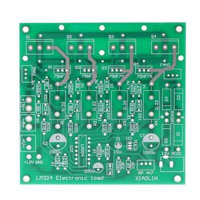
-The kit, as shown in the main figure, does not contain a dual display head and a heatsink.
-Board size 10 * 10cm
-Installed TO-220 package of the tube, heat sink fixed to the board, then the following pad a temperature insulation film, to prevent short-circuit below the TO-247 pad.
Specifications:
input voltage : 0-15v /0-72V
load current :0-10A/0-2A
The basic circuit form is the TL431 providing the reference voltage, the sense resistor, and the op amp error amplification.
Together with the MOS tube constant current circuit. Used 4 MOS tubes.
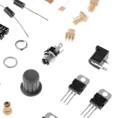
Kit contains 4 110N8F6 110A 80V for TO-220 package
The original circuit parameters: 75NF75 75V 75A 150W
Substitution: Model 80NF70 IRF3205 HRF3250 IRF1010 IRF2807 IRF1405 047an08ao and so on
Also available with IRF 250 260 and other TO-247 encapsulated tubes
Board size 10*10cm
When the board is powered by a 12V switching power supply, four rectifiers can be disconnected
The heat sink and 12V DC negative pole can not conduct with the metal shell at the same time!
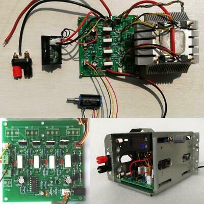
When the board is connected to the digital dual display meter
The power supply of the meter's red wire is connected to the +12V thin black wire without connecting to GND (there is no current access)!
A+ - Coarse current and red line at the head of the meter V+ Voltage at the head of the meter to test the thin yellow line
IN is the test input. Connect the red and black test terminals to the tested power supply.
Note:
The positive and negative poles of the tested power supply must not be reversed, otherwise it will burn out the breakdown MOS power transistor!
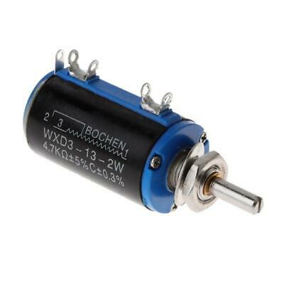
Knobs open the caps and tighten them to tighten them.
The power tube is coated with thermal grease and tightened directly onto the heat sink.
Must be connected to the radiator after power debugging! Otherwise or burn out the power tube!
Package Included:
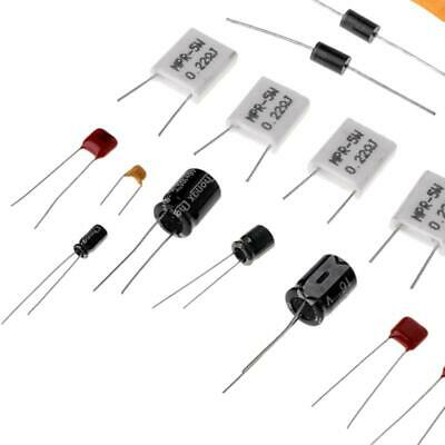
1 x Simple Electronic Load Tester DIY Kit (not assembled)
